Click the button below to access our complete guide TERRAGRIF
our complete guide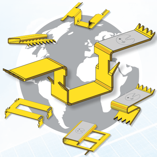
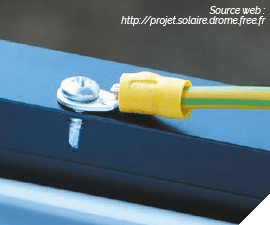
According to the UTE C157-12 Guide, the grounding of metal and conductive elements of the direct current section is intended to «minimize the effects due to induced overvoltages, metal structures of modules and metal supporting structures (including metal cable trays) must be linked to a safety equipotential bonding which is connected to the ground. Since these metal structures are generally made of aluminum, suitable connection devices should be used. The work of grounding the PV modules is carried out in accordance with the manufacturer’s instructions»
The frames of photovoltaic modules make it possible to ensure an essential mechanical resistance, and to create an equipotentiality mesh. This mesh will make it possible to control overvoltages connected to lightning, and to limit the damage to the modules during arc faults between the structure and active conductors.
This mesh only works if the interconnections of the metal parts are carried out properly, either by wired connections (obligatory to have a grounding connection point) or by means of our TerraGrif™ system.
IEC 61730-2 (2004) + A1 (2011):
Qualification standard framework for the operating safety of photovoltaic modules
IEC 60439-1 (2004) -§8.2.4.1:
Ground continuity resistance measurement
NF EN 60068-2-11:
Salt spray test
NF EN 61180-1:
Lightning test
NF EN 61215 : 2015:
Thermal cycling test
When implementing photovoltaic facilities and using traditional grounding solutions, we have noted various shortcomings and many risks with regard to this solution.
The rings used to fix grounding modules claim to perform the two functions of fixing and grounding. In theory, this dual function seems ideal. However, in reality, the facts are less idyllic!
With or without wiring, the earthing function of a fixing ring is directly and solely related to the tightening torque of the fixing ring. The difficulty lies in knowing how to ensure ideal tightening, recommended by the manufacturer of the mounting system and the panel manufacturer. This solution is also dependent on the expansion and temperature cycling and is not sustainable over time.
In pratice:
With a loose fixing ring, the grounding is not properly completed and there is a very high risk.
This action alone will immediately result in the panel losing its product warranty as soon as it is installed. We invite you to carefully read the PV mo-dules’ product data sheets and installation instructions.
This information is clearly confirmed by panel manufacturers.
The certificates issued by the inspection body LCIE relating to fixing rings only very rarely concern the grounding part. They only concern the fixing of the panels.
We invite you to check with your suppliers the protocol used to obtain this certificate and to check that the grounding part is included in it. The LCIE certificate must mention it.
The LCIE certificate for fixing rings obtained by mounting system designers does not validate the reservations made by the panel manufacturers.
Inspection bodies along with insurance companies are becoming increasingly intransigent with regard to meeting these obligations.
It should also be noted that these same rings have to be tightened again every 5 years, to ensure the efficiency of the grounding and the fixing of the panels. This operation is actually never carried out.
In short, so many immediate constraints when setting up the facility and over the long term! As evidence of this, in the guide you will find excerpts from texts in the installation manuals for various companies’ photovoltaic panels.
The objective of the TerraGrif™ part is to carry out the equipotentiality of the aluminium frame of the PV panels and the mounting system.
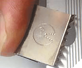
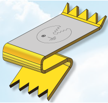
It is a steel spring part positioned between the PV panel and the mounting bracket, with specific sets of teeth making it possible to grip the 2 different brackets.
The TerraGrif™ part penetrates the non-conductive coating of the PV frame by destroying this anodised layer of the frame.
This solution is patented (Publication No. WO 2012/123797).
The TerraGrif™ is designed and made according to the mounting structure implemented, and according to the various PV panels which will be used. There are several types of TerraGrif™.
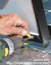
The TerraGrif™ is in contact with the return side/under the frame of the module, either by being pressed or by interlocking it or pinching it.
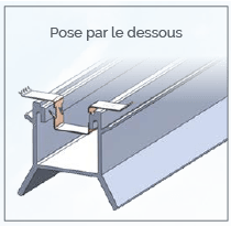
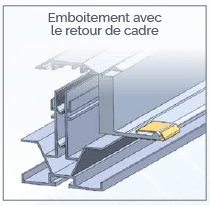
During the implementation, this interlocking is facilitated by the shape and geometry of the claws.
The TerraGrif™ is held by anchoring the claws in the frame material and mounting system. The force of the spring and this geometry prevents the claw from being withdrawn. The expansion of the aluminium has very little influence given that the spring action of the TerraGrif™ counteracts this effect.
All the TerraGrif™ parts are subject to a certification protocol by the LCIE VERITAS inspection body. We We would like to point out that before the tests for the TerraGrif™ product were launched, there was no test protocol.
Mobasolar, with the support of professionals from the energy sector and the LCIE VERITAS laboratory, established a precise protocol which today governs all grounding tests. This protocol was etablished in accordance current standards.
Test Protocol: 4 constraints are checked during the tests (opposite): The LCIE VERITAS results
According to the regulations in force (IEC 61730-2 and IEC 60439-1 standards), the value of the resistance between the frame of the photovoltaic panel and the mounting system connected to the TerraGrif™ has to be less than 100 mOhm.
The value is determined by measuring the voltage drop, via the ratio Rc = U / I.
LCIE VERITAS only considers the test as satisfactory if the resistance value of the first three tests is less than 100 mOhm.
With the TerraGrif™ solution, the results are:
THE TerraGrif™ SOLUTION FULLY COMPLIES WITH THE STANDARD AND EVEN GOES FURTHER:
SINCE 2018, THE TerraGrif™ SOLUTION HAS BEEN PRESENT IN:
With these excellent results and increasingly effective R&D work, it is therefore not surprising that the TerraGrif™ grounding part has been referenced and approved for many years by most manufacturers of:
This trust in TerraGrif™ is strong and solid. It has been recognized by our customers for many years and by inspection and certification bodies such as QUALIT ENR, CSTB, EST PREVENTION, APAVE, DEKRA, SOCOTEC…